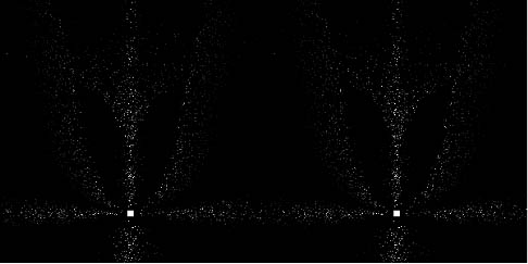
For quite a long time I was wondering how halos in nearby ice crystals, especially when caused by divergent light, are perceived spatially. The AKM halo meeting at the Sudelfeld, Germany in January 2010 has intensified this interest once more, and I tried to capture some stereo pictures with two cameras on conventional slide film. Unfortunately, the results were not as convincing as expected, and there was no further opportunity for me to watch an actual display this season. So I decided to do some computational work instead. I started with the analytical calculations of halo surfaces by Walter Tape ( 1 ) and was curious to see what would come out for two eyes instead of a single observer. The (at least for me) surprising answer was that there should be no stereoscopic depth impression for all the halo surfaces (two Minnaert cigars starting at the lamp and ending in the individual eyes, and so on), they simply appear pinned to a plane through the lamp perpendicular to the direction of sight. This holds true even for the “eye-connected” halos such as the 22° ring or parhelia. This was an unsatisfying result, since I knew from observations during the halo meeting that there is a certain spatial impression in an ice crystal display, especially for the tangent arcs that appear partially much closer to the observer than the lamp. How can this puzzle be solved?
I suggest the following explanation: The ice crystal halo display is not made simply from idealized halo surfaces (or, more general, from an intensity field in space which takes into account all the subtle intensity variations along parhelia, tangent arcs, and so on) rather than from individual crystals that fall down or drift around in space and sample the intensity field pointwise along their trajectories. These crystals are real physical objects and should be perceived stereoscopically at their actual position, if being illuminated externally at equal brightness for each eye. But in case of a streetlight halo they deflect light by themselves to the observer according to the intensity field which lies stereoscopically flat around the lamp. Thus, especially crystals near to the observer should not appear at equal intensity for both eyes. But as long as both eyes receive light without any large difference in intensity the crystal should be perceived at its actual position and not pinned to some plane in the lamp’s distance, and so we get the stereoscopic depth impression of the halo display. This also implies that on a long-exposed stereo photo all contributions form individual crystal trajectories should be averaged, which would lead to a smooth and stereoscopically flat image of the intensity field.
At this point, I had the idea of an animated simulation. Spatial perception is still not fully understood physiologically, and there might also be an influence of dynamic effects from the moving crystals as well. So some kind of stereo animation should be the suitable representation of the problem, and then we can leave the interpretation work to the brain just like in a real display. I started the computation with typically 200000 random crystal positions in a cube between observer and light source that were tracked for 100 time steps. From one step to the next the crystals move a small distance downwards (when reaching the ground, a new position is generated to prevent from loosing the crystals). From geometry, it is quite easy to calculate the intensity for different halo species if the intensity field is provided as some look-up table or analytical fit. This is done separately for each eye. The images linked below show the results for cross-eyed viewing (left image on the right side) and as anaglyph (left image red).
The included halo species are super/sublamps, 22° super/subparhelia, 22° parhelia, and 22° tangent arcs. The distance observer-lamp (in horizontal projection) is 10 m, the lamp elevation is +5° for the first and –5° for the second series. For the first simulation, the field of view corresponds to a 28 mm lens on 35 mm film (cropped to a square area), for the second it corresponds to 20 mm. The histogram had to be cropped at the white edge and the gamma value was increased as well since the original images that were normalized with respect to the brightest pixel would appear much to dark.
There are some simplifications in the model that I don’t want to conceal: No colour dispersion for refraction halos was taken into account, all calculations were done with a fixed index of refraction. Diffraction and defocus blurring were also neglected, each crystal is assigned to a single pixel (but more than one crystal can contribute to the brightness information of one pixel). The intensity ratios between the halo species were set arbitrarily and are not determined by a predefined set of crystals with certain orientations, aspect ratios, and so on. A subtle matter is that remaining degrees of freedom (such as the rotation angle around the vertical axis for parhelia oriented crystals) are already averaged by taking the intensity from a look-up table and not assigning these degrees of freedom to the simulated crystal the same way as it was done with the spatial coordinates. Otherwise the computation time would have increased dramatically. So I did not simulate individual crystals in this sense, or otherwise I have to assume that they are spinning around their allowed axes at quite a high speed in order to do the averaging.
Nonetheless, it can be seen quite nicely from the animations that eye-connected halos (parhelia, upper tangent arc for positive lamp elevation, “super”parhelia at negative lamp elevation…) near their classical positions – when crystals close to the observer are involved – seem to pop out of the screen and show a distinct stereoscopic depth impression.
Kind regards,
Alexander Haußman

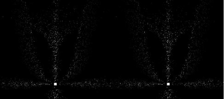

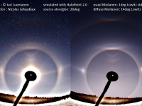
Maybe I am doing something wrong, but the tangent arc is behind the pillar and the opposite direction that it should be. And for parhelia I can’t get any 3D effect. The superparhelia somewhat looks like it should be.
Hi Marko, maybe you tried parallel instead of cross-eyed viewing. The effect for parhelia is visible near the 22° position, near the edges of the image. Possibly these edges are disturbing.